- Table of Contents
- Related Documents
-
| Title | Size | Download |
|---|---|---|
| 01-gRPC configuration | 183.56 KB |
Contents
Telemetry technology based on gRPC
Configuring the gRPC dial-in mode
gRPC dial-in mode configuration tasks at a glance
Configuring the gRPC dial-out mode
gRPC dial-out mode configuration tasks at a glance
Display and maintenance commands for gRPC
Example: Configuring the gRPC dial-in mode
Example: Configuring the gRPC dial-out mode
Proto definition files in dial-in mode
Proto definition file in dial-out mode
Obtaining proto definition files
Example: Developing a gRPC collector-side application
Generating the C++ code for the proto definition files
Developing the collector-side application
Configuring gRPC
About gRPC
gRPC is an open source remote procedure call (RPC) system initially developed at Google. It uses HTTP 2.0 for transport and provides network device configuration and management methods that support multiple programming languages.
gRPC protocol stack layers
Table 1 describes the gRPC protocol stack layers.
Table 1 gRPC protocol stack layers
|
Layer |
Description |
|
Content layer |
Defines the data of the service module. Two peers must notify each other of the data models that they are using. |
|
Protocol buffer encoding layer |
Encodes data by using the protocol buffer code format. |
|
gRPC layer |
Defines the protocol interaction format for remote procedure calls. |
|
HTTP 2.0 layer |
Carries gRPC. |
|
TCP layer |
Provides connection-oriented reliable data links. |
Network architecture
As shown in Figure 1, the gRPC network uses the client/server model. It uses HTTP 2.0 for packet transport.
Figure 1 gRPC network architecture
![]()
The gRPC network uses the following mechanism:
1. The gRPC server listens to connection requests from clients at the gRPC service port.
2. A user runs the gRPC client application to log in to the gRPC server, and uses methods provided in the .proto file to send requests.
3. The gRPC server responds to requests from the gRPC client.
The device can act as the gRPC server or client.
Telemetry technology based on gRPC
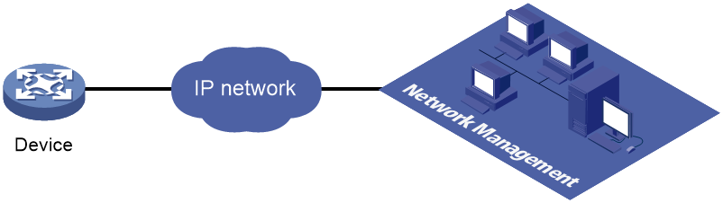
Telemetry is a remote data collection technology for monitoring device performance and operating status. H3C telemetry technology uses gRPC to push data from the device to the collectors on the NMSs. As shown in Figure 2, after a gRPC connection is established between the device and NMSs, the NMSs can subscribe to data of modules on the device.
Figure 2 Telemetry technology based on gRPC
Telemetry modes
The device supports the following telemetry modes:
· Dial-in mode—The device acts as a gRPC server and the collectors act as gRPC clients. A collector initiates a gRPC connection to the device to subscribe to device data.
Dial-in mode applies to small networks where collectors need to deploy configurations to devices.
· Dial-out mode—The device acts as a gRPC client and the collectors act as gRPC servers. The device initiates a gRPC connection to the collectors and pushes subscribed device data to the collectors.
Dial-out mode applies to larger networks where devices need to push device data to collectors.
Protocols
RFC 7540, Hypertext Transfer Protocol version 2 (HTTP/2)
FIPS compliance
The device supports the FIPS mode that complies with NIST FIPS 140-2 requirements. Support for features, commands, and parameters might differ in FIPS mode and non-FIPS mode. For more information about FIPS mode, see Security Configuration Guide.
gRPC is not supported in FIPS mode.
Prerequisites for gRPC
Before you can configure gRPC, you must install a gRPC feature software image compatible with the device software version. For information about the installation procedure, see software upgrade configuration in Fundamentals Configuration Guide.
Configuring the gRPC dial-in mode
gRPC dial-in mode configuration tasks at a glance
To configure the gRPC dial-in mode, perform the following tasks:
1. Configuring the gRPC service
Configuring the gRPC service
Restrictions and guidelines
If the gRPC service fails to be enabled, use the display tcp or display ipv6 tcp command to verify whether the gRPC service port number has been used by another feature. If yes, specify a free port as the gRPC service port number and try to enable the gRPC service again. For more information about the display tcp and display ipv6 tcp commands, see Layer 3—IP Services Command Reference.
Procedure
1. Enter system view.
system-view
2. (Optional.) Set the gRPC service port number.
grpc port port-number
By default, the gRPC service port number is 50051.
Changing the gRPC service port number reboots the gRPC service and disconnects all sessions established between the gRPC server and its gRPC clients. The gRPC clients must reinitiate the sessions.
3. Enable the gRPC service.
grpc enable
By default, the gRPC service is disabled.
4. (Optional.) Set the gRPC session idle timeout timer.
grpc idle-timeout minutes
By default, the gRPC session idle timeout timer is 5 minutes.
Configuring a gRPC user
About gRPC users
For gRPC clients to establish gRPC sessions with the device, you must configure local users for the gRPC clients.
Procedure
1. Enter system view.
system-view
2. Add a local user with the device management right.
local-user user-name [ class manage ]
3. Configure a password for the user.
password [ { hash | simple } password ]
By default, no password is configured for a local user. A non-password-protected user can pass authentication after providing the correct username and passing attribute checks.
4. Assign user role network-admin to the user.
authorization-attribute user-role user-role
By default, a local user is assigned the network-operator role.
5. Authorize the user to use the HTTPS service.
service-type https
By default, no service types are authorized to a local user.
For more information about the local-user, password, authorization-attribute, and service-type commands, see AAA configuration in Security Command Reference.
Configuring the gRPC dial-out mode
gRPC dial-out mode configuration tasks at a glance
To configure the gRPC dial-out mode, perform the following tasks:
Enabling the gRPC service
1. Enter system view.
system-view
2. Enable the gRPC service.
grpc enable
By default, the gRPC service is disabled.
Configuring sensors
About sensors
The device uses sensors to sample data. A sensor path indicates a data source.
Supported data sampling types include:
· Event-triggered sampling—Sensors in a sensor group sample data when certain events occur. For sensor paths of this data sampling type, see NETCONF XML API Event Reference for the module.
· Periodic sampling—Sensors in a sensor group sample data at intervals. For sensor paths of this data sampling type, see the NETCONF XML API references for the module except for NETCONF XML API Event Reference.
Procedure
1. Enter system view.
system-view
2. Enter telemetry view.
telemetry
3. Create a sensor group and enter sensor group view.
sensor-group group-name
4. Specify a sensor path.
sensor path path
To specify multiple sensor paths, execute this command multiple times.
Configuring collectors
About collectors
Collectors are used to receive sampled data from network devices. For the device to communicate with collectors, you must create a destination group and add collectors to the destination group.
You can add collectors to a destination group by their IP addresses or domain names When you specify collectors by their domain names, use the following restrictions and guidelines:
· You must configure DNS to make sure the device can translate the domain names of the collectors to IP addresses. For more information about DNS, see Layer 3—IP Services Configuration Guide.
· To view domain name and IP address mappings, use the display dns host command. If a domain name maps to multiple IP addresses, the device will push data to the first reachable IP address.
Restrictions and guidelines
As a best practice, configure a maximum of five destination groups. If you configure too many destination groups, system performance might degrade.
Prerequisites
To configure a collector that resides in a VPN instance, configure the VPN instance first.
Procedure
1. Enter system view.
system-view
2. Enter telemetry view.
telemetry
3. Create a destination group and enter destination group view.
destination-group group-name
4. Specify a collector.
IPv4:
ipv4-address ipv4-address [ port port-number ] [ vpn-instance vpn-instance-name ]
IPv6:
ipv6-address ipv6-address [ port port-number ] [ vpn-instance vpn-instance-name ]
To add multiple collectors, repeat this command. A collector is uniquely identified by a three-tuple of IP address, port number, and VPN instance name. One collector must have a different IP address, port number, or VPN instance name than the other collectors in the destination group.
5. Add a collector to the destination group by its domain name.
IPv4:
domain-name domain-name [ port port-number ] [ vpn-instance vpn-instance-name ]
IPv6:
ipv6 domain-name domain-name [ port port-number ] [ vpn-instance vpn-instance-name ]
To add multiple collectors, repeat this command. A collector is uniquely identified by a three-tuple of domain name, port number, and VPN instance name. One collector must have a different domain name, port number, or VPN instance name than the other collectors in the destination group.
Configuring a subscription
About configuring a subscription
A subscription binds sensor groups to destination groups. Then, the device pushes data from the specified sensors to the collectors.
Procedure
1. Enter system view.
system-view
2. Enter telemetry view.
telemetry
3. Create a subscription and enter subscription view.
subscription subscription-name
4. (Optional.) Specify the source IP address for packets sent to collectors.
source-address { ipv4-address | interface interface-type interface-number | ipv6 ipv6-address }
By default, the device uses the primary IPv4 address of the output interface for the route to the collectors as the source address.
Changing the source IP address for packets sent to collectors causes the device to re-establish the connection to the gRPC server.
5. Specify a sensor group.
sensor-group group-name [ sample-interval interval ]
Specify the sample-interval interval option for periodic sensor paths and only for periodic sensor paths.
¡ If you specify the option for event-triggered sensor paths, the sensor paths do not take effect.
¡ If you do not specify the option for periodic sensor paths, the device does not sample or push data.
6. Specify a destination group.
destination-group group-name
Display and maintenance commands for gRPC
Execute display commands in any view.
|
Task |
Command |
|
Display gRPC information. |
display grpc [ verbose ] |
gRPC configuration examples
These configuration examples describe only CLI configuration tasks on the device. The collectors need to run an extra application. For information about collector-side application development, see "Developing the collector-side application."
Example: Configuring the gRPC dial-in mode
Network configuration
As shown in Figure 3, configure the gRPC dial-in mode on the device so the device acts as the gRPC server and the gRPC client can subscribe to LLDP events on the device.

Prerequisites
Before you can configure gRPC, you must install a gRPC feature software image compatible with the device software version. For more information about the installation procedure, see software upgrade configuration in Fundamentals Configuration Guide.
To install a gRPC feature software image:
1. Download the gRPC feature software image compatible with the device software version from the H3C website to the root directory of the flash memory on the device. On an IRF fabric, download the image file to the root directory of the flash memory on the device. (Details not shown.)
2. Install the feature software image on the device and commit the software change. On an IRF fabric, install the image on each member device. For example, install the image on the member device with an IRF member ID of 1 for the slot number.
<Device> install activate feature flash:/grpc-01.bin slot 1
Verifying the file flash:/grpc-01.bin on slot 1....Done.
Identifying the upgrade methods....Done.
Upgrade summary according to following table:
flash:/grpc-01.bin
Running Version New Version
None Demo 01
Slot Upgrade Way
1 Service Upgrade
Upgrading software images to compatible versions. Continue? [Y/N]:y
This operation might take several minutes, please wait....................Done.
<Device> install commit
This operation will take several minutes, please wait.......................Done.
3. Log in to the device or the IRF fabric again.
Procedure
1. Assign IP addresses to interfaces on the gRPC server and client and configure routes. Make sure the server and client can reach each other.
2. Configure the device as the gRPC server:
# Enable the gRPC service.
<Device> system-view
[Device] grpc enable
# Create a local user named test. Set the password to test, and assign user role network-admin and the HTTPS service to the user.
[Device] local-user test
[Device-luser-manage-test] password simple test
[Device-luser-manage-test] authorization-attribute user-role network-admin
[Device-luser-manage-test] service-type https
[Device-luser-manage-test] quit
3. Configure the gRPC client.
a. Prepare a PC and install the gRPC environment on the PC. For more information, see the user guide for the gRPC environment.
b. Obtain the H3C proto definition file and uses the protocol buffer compiler to generate code of a specific language, for example, Java, Python, C/C++, or Go.
c. Create a client application to call the generated code.
d. Start the application to log in to the gRPC server.
Verifying the configuration
When an LLDP event occurs on the gRPC server, verify that the gRPC client receives the event.
Example: Configuring the gRPC dial-out mode
Network configuration
As shown in Figure 4, the device is connected to a collector. The collector uses port 50050.
Configure gRPC dial-out mode on the device so the device pushes the device capability information of its interface module to the collector at 10-second intervals.

Prerequisites
Before you can configure gRPC, you must install a gRPC feature software image compatible with the device software version. For more information about the installation procedure, see software upgrade configuration in Fundamentals Configuration Guide.
To install a gRPC feature software image:
1. Download the gRPC feature software image compatible with the device software version from the H3C website to the root directory of the flash memory on the device. On an IRF fabric, download the image file to the root directory of the flash memory on the device. (Details not shown.)
2. Install the feature software image on the device and commit the software change. On an IRF fabric, install the image on each member device. For example, install the image on the member device with an IRF member ID of 1 for the slot number.
<Device> install activate feature flash:/grpc-01.bin slot 1
Verifying the file flash:/grpc-01.bin on slot 1....Done.
Identifying the upgrade methods....Done.
Upgrade summary according to following table:
flash:/grpc-01.bin
Running Version New Version
None Demo 01
Slot Upgrade Way
1 Service Upgrade
Upgrading software images to compatible versions. Continue? [Y/N]:y
This operation might take several minutes, please wait....................Done.
<Device> install commit
This operation will take several minutes, please wait.......................Done.
3. Log in to the device or the IRF fabric again.
Procedure
# Configure IP addresses as required so the device and the collector can reach each other. (Details not shown.)
# Enable the gRPC service.
<Device> system-view
[Device] grpc enable
# Create a sensor group named test, and add sensor path ifmgr/devicecapabilities/.
[Device] telemetry
[Device-telemetry] sensor-group test
[Device-telemetry-sensor-group-test] sensor path ifmgr/devicecapabilities/
[Device-telemetry-sensor-group-test] quit
# Create a destination group named collector1. Specify a collector that uses IPv4 address 192.168.2.1 and port number 50050.
[Device-telemetry] destination-group collector1
[Device-telemetry-destination-group-collector1] ipv4-address 192.168.2.1 port 50050
[Device-telemetry-destination-group-collector1] quit
# Configure a subscription named A to bind sensor group test with destination group collector1. Set the sampling interval to 10 seconds.
[Device-telemetry] subscription A
[Device-telemetry-subscription-A] sensor-group test sample-interval 10
[Device-telemetry-subscription-A] destination-group collector1
[Device-telemetry-subscription-A] quit
Verifying the configuration
# Verify that the collector receives the device capability information of the interface module from the device at 10-second intervals. (Details not shown.)
Protocol buffer code
Protocol buffer code format
Google Protocol Buffers provide a flexible mechanism for serializing structured data. Different from XML code and JSON code, the protocol buffer code is binary and provides higher performance.
Table 2 compares a protocol buffer code format example and the corresponding JSON code format example.
Table 2 Protocol buffer and JSON code format examples
|
Protocol buffer code format example |
Corresponding JSON code format example |
|
{ 1:“H3C” 2:“H3C” 3:“H3C Simware” 4:“Syslog/LogBuffer” 5:"notification": { "Syslog": { "LogBuffer": { "BufferSize": 512, "BufferSizeLimit": 1024, "DroppedLogsCount": 0, "LogsCount": 100, "LogsCountPerSeverity": { "Alert": 0, "Critical": 1, "Debug": 0, "Emergency": 0, "Error": 3, "Informational": 80, "Notice": 15, "Warning": 1 }, "OverwrittenLogsCount": 0, "State": "enable" } }, "Timestamp": "1527206160022" } } |
{ "producerName": "H3C", "deviceName": "H3C", "deviceModel": "H3C Simware", "sensorPath": "Syslog/LogBuffer", "jsonData": { "notification": { "Syslog": { "LogBuffer": { "BufferSize": 512, "BufferSizeLimit": 1024, "DroppedLogsCount": 0, "LogsCount": 100, "LogsCountPerSeverity": { "Alert": 0, "Critical": 1, "Debug": 0, "Emergency": 0, "Error": 3, "Informational": 80, "Notice": 15, "Warning": 1 }, "OverwrittenLogsCount": 0, "State": "enable" } }, "Timestamp": "1527206160022" } } } |
Proto definition files
You can define data structures in a proto definition file. Then, you can compile the file with utility protoc to generate code in a programing language such as Java and C++. Using the generated code, you can develop an application for a collector to communicate with the device.
H3C provides proto definition files for both dial-in mode and dial-out mode.
Proto definition files in dial-in mode
Public proto definition files
The grpc_service.proto file defines the public RPC methods in dial-in mode, for example, login method and logout method.
The following are the contents of the grpc_service.proto file:
syntax = "proto2";
package grpc_service;
message GetJsonReply { // Reply to the Get method
required string result = 1;
}
message SubscribeReply { // Subscription result
required string result = 1;
}
message ConfigReply { // Configuration result
required string result = 1;
}
message ReportEvent { // Subscribed event
required string token_id = 1; // Login token_id
required string stream_name = 2; // Event stream name
required string event_name = 3; // Event name
required string json_text = 4; // Subscription result, a JSON string
}
message GetReportRequest{ // Obtains the event subscription result
required string token_id = 1; // Returns the token_id upon a successful login
}
message LoginRequest { // Login request parameters
required string user_name = 1; // Username
required string password = 2; // Password
}
message LoginReply { // Reply to a login request
required string token_id = 1; // Returns the token_id upon a successful login
}
message LogoutRequest { // Logout parameter
required string token_id = 1; // token_id
}
message LogoutReply { // Reply to a logout request
required string result = 1; // Logout result
}
message SubscribeRequest { // Event stream name
required string stream_name = 1;
}
service GrpcService { // gRPC methods
rpc Login (LoginRequest) returns (LoginReply) {} // Login method
rpc Logout (LogoutRequest) returns (LogoutReply) {} // Logout method
rpc SubscribeByStreamName (SubscribeRequest) returns (SubscribeReply) {} // Event subscription method
rpc GetEventReport (GetReportRequest) returns (stream ReportEvent) {} // Method for obtaining the subscribed event
}
Proto definition files for service modules
The dial-in mode supports proto definition files for the following service modules: Device, Ifmgr, IPFW, LLDP, and Syslog.
The following are the contents of the Device.proto file, which defines the RPC methods for the Device module:
syntax = "proto2";
import "grpc_service.proto";
package device;
message DeviceBase { // Structure for obtaining basic device information
optional string HostName = 1; // Device name
optional string HostOid = 2; // sysoid
optional uint32 MaxChassisNum = 3; //Maximum number of chassis
optional uint32 MaxSlotNum = 4; // Maximum number of slots
optional string HostDescription = 5; // Device description
}
message DevicePhysicalEntities { // Structure for obtaining physical entity information of the device
message Entity {
optional uint32 PhysicalIndex = 1; // Entity index
optional string VendorType = 2; // Vendor type
optional uint32 EntityClass = 3; // Entity class
optional string SoftwareRev = 4; // Software version
optional string SerialNumber = 5; // Serial number
optional string Model = 6; // Model
}
repeated Entity entity = 1;
}
service DeviceService { // RPC methods
rpc GetJsonDeviceBase(DeviceBase) returns (grpc_service.GetJsonReply) {} // Method for obtaining basic device information
rpc GetJsonDevicePhysicalEntities(DevicePhysicalEntities) returns (grpc_service.GetJsonReply) {} // Method for obtaining physical entity information of the device
}
Proto definition file in dial-out mode
The grpc_dialout.proto file defines the public RPC methods in dial-out mode. The following are the contents of the file:
syntax = "proto2";
package grpc_dialout;
message DeviceInfo{ // Pushed device information
required string producerName = 1; // Vendor name
required string deviceName = 2; // Device name
required string deviceModel = 3; // Device model
}
message DialoutMsg{ // Format of the pushed data
required DeviceInfo deviceMsg = 1; // Device information described by DeviceInfo
required string sensorPath = 2; // Sensor path, which corresponds to xpath in NETCONF
required string jsonData = 3; // Sampled data, a JSON string
}
message DialoutResponse{ // Response from the collector. Reserved. The value is not processed.
required string response = 1;
}
service gRPCDialout { // Data push method
rpc Dialout(stream DialoutMsg) returns (DialoutResponse);
}
Obtaining proto definition files
Contact the technical support.
Example: Developing a gRPC collector-side application
Use a language (for example, C++) to develop a gRPC collector-side application on Linux to enable a collector to collect device data.
Prerequisites
1. Obtain H3C proto definition files.
¡ For dial-in mode, obtain the grpc_service.proto file and proto definition files for service modules.
¡ For dial-out mode, obtain the grpc_dialout.proto file.
2. Obtain utility protoc from https://github.com/google/protobuf/releases.
3. Obtain the protobuf plug-in for C++ (protobuf-cpp) from https://github.com/google/protobuf/releases.
Generating the C++ code for the proto definition files
Dial-in mode
# Copy the required proto definition files to the current directory, for example, grpc_service.proto and BufferMonitor.proto.
$protoc --plugin=./grpc_cpp_plugin --grpc_out=. --cpp_out=. *.proto
Dial-out mode
# Copy proto definition file grpc_dialout.proto to the current directory.
$ protoc --plugin=./grpc_cpp_plugin --grpc_out=. --cpp_out=. *.proto
Developing the collector-side application
Dial-in mode
In dial-in mode, the application needs to provide the code to be run on the gRPC client.
The C++ code generated from the proto definition files already encapsulates the service classes, which are GrpcService and BufferMonitorService in this example. For the gRPC client to initiate RPC requests, you only need to call the RPC method in the application.
The application performs the following operations:
· Log in to obtain the token_id.
· Prepare parameters for the RPC method, use the service classes generated from the proto definition files to call the RPC method, and resolve the returned result.
· Log out.
To develop the collector-side application in dial-in mode:
1. Create a GrpcServiceTest class.
# In the class, use the GrpcService::Stub class generated from grpc_service.proto. Implement login and logout with the Login and Logout methods generated from grpc_service.proto.
class GrpcServiceTest
{
public:
/* Constructor functions */
GrpcServiceTest(std::shared_ptr<Channel> channel): GrpcServiceStub(GrpcService::NewStub(channel)) {}
/* Member functions */
int Login(const std::string& username, const std::string& password);
void Logout();
void listen();
/* Member variable */
std::string token;
private:
std::unique_ptr<GrpcService::Stub> GrpcServiceStub; // Use the GrpcService::Stub class generated from grpc_service.proto.
};
2. Customize the Login method.
# Call the Login method of the GrpcService::Stub class to allow a user who provides the correct the username and password to log in.
int GrpcServiceTest::Login(const std::string& username, const std::string& password)
{
LoginRequest request; // Username and password.
request.set_user_name(username);
request.set_password(password);
LoginReply reply;
ClientContext context;
// Call the Login method.
Status status = GrpcServiceStub->Login(&context, request, &reply);
if (status.ok())
{
std::cout << "login ok!" << std::endl;
std::cout <<"token id is :" << reply.token_id() << std::endl;
token = reply.token_id(); // The login succeeds. The token is obtained.
return 0;
}
else{
std::cout << status.error_code() << ": " << status.error_message()
<< ". Login failed!" << std::endl;
return -1;
}
}
3. Initiate an RPC request to the device. In this example, the application subscribes to interface packet drop events.
rpc SubscribePortQueDropEvent(PortQueDropEvent) returns (grpc_service.SubscribeReply) {}
4. Create the BufMon_GrpcClient class to encapsulate the RPC method.
# Use the BufferMonitorService::Stub class generated from BufferMonitor.proto to call the RPC method.
class BufMon_GrpcClient
{
public:
BufMon_GrpcClient(std::shared_ptr<Channel> channel): mStub(BufferMonitorService::NewStub(channel))
{
}
std::string BufMon_Sub_AllEvent(std::string token);
std::string BufMon_Sub_BoardEvent(std::string token);
std::string BufMon_Sub_PortOverrunEvent(std::string token);
std::string BufMon_Sub_PortDropEvent(std::string token);
/* Get entries */
std::string BufMon_Sub_GetStatistics(std::string token);
std::string BufMon_Sub_GetGlobalCfg(std::string token);
std::string BufMon_Sub_GetBoardCfg(std::string token);
std::string BufMon_Sub_GetNodeQueCfg(std::string token);
std::string BufMon_Sub_GetPortQueCfg(std::string token);
private:
std::unique_ptr<BufferMonitorService::Stub> mStub; // Use the class generated from BufferMonitor.proto.
};
5. Use std::string BufMon_Sub_PortDropEvent(std::string token) to implement interface packet drop event subscription.
std::string BufMon_GrpcClient::BufMon_Sub_PortDropEvent(std::string token)
{
std::cout << "-------BufMon_Sub_PortDropEvent-------- " << std::endl;
PortQueDropEvent stNodeEvent;
PortQueDropEvent_PortQueDrop* pstParam = stNodeEvent.add_portquedrop();
UINT uiIfIndex = 0;
UINT uiQueIdx = 0;
UINT uiAlarmType = 0;
std::cout<<"Please input interface queue info : ifIndex queIdx alarmtype " << std::endl;
cout<<"alarmtype : 1 for ingress; 2 for egress; 3 for port headroom"<<endl;
std::cin>>uiIfIndex>>uiQueIdx>>uiAlarmType; // Set the subscription parameters and interface index.
pstParam->set_ifindex(uiIfIndex);
pstParam->set_queindex(uiQueIdx);
pstParam->set_alarmtype(uiAlarmType);
ClientContext context;
/* Token needs to be added to context */ // Set the token_id to be returned after a successful login
std::string key = "token_id";
std::string value = token;
context.AddMetadata(key, value);
SubscribeReply reply;
Status status = mStub->SubscribePortQueDropEvent(&context,stNodeEvent,&reply); // Call the RPC method.
return reply.result();
}
6. Use a loop to listen to event reports.
# Implement this method in the GrpcServiceTest class.
void GrpcServiceTest::listen()
{
GetReportRequest reportRequest;
ClientContext context;
ReportEvent reportedEvent;
/* Add the token to the request */
reportRequest.set_token_id(token);
std::unique_ptr< ClientReader< ReportEvent>> reader(GrpcServiceStub->GetEventReport(&context, reportRequest)); // Use GetEventReport (which is generated from grpc_service.proto) to obtain event information.
std::string streamName;
std::string eventName;
std::string jsonText;
std::string token;
JsonFormatTool jsonTool;
std::cout << "Listen to server for Event" << std::endl;
while(reader->Read(&reportedEvent) ) // Read the received event report.
{
streamName = reportedEvent.stream_name();
eventName = reportedEvent.event_name();
jsonText = reportedEvent.json_text();
token = reportedEvent.token_id();
std::cout << "/**********************EVENT COME************************/" << std::endl;
std::cout << "TOKEN: " << token << std::endl;
std::cout << "StreamName: "<< streamName << std::endl;
std::cout << "EventName: " << eventName << std::endl;
std::cout << "JsonText without format: " << std::endl << jsonText << std::endl;
std::cout << std::endl;
std::cout << "JsonText Formated: " << jsonTool.formatJson(jsonText) << std::endl;
std::cout << std::endl;
}
Status status = reader->Finish();
std::cout << "Status Message:" << status.error_message() << "ERROR code :" << status.error_code();
} // Login and RPC request finished.
7. To log out, call the Logout method. (Details not shown.)
Dial-out mode
In dial-out mode, the application needs to provide the gRPC server code so the collector can receive and resolve data obtained from the device.
The application performs the following operations:
· Inherit the automatically generated GRPCDialout::Service class, overload the automatically generated RPC Dialout service, and resolve the fields.
· Register the RPC service with the specified listening port.
To develop the collector-side application in dial-out mode:
1. Inherit and overload RPC service Dialout.
# Create class DialoutTest and inherit GRPCDialout::Service.
class DialoutTest final : public GRPCDialout::Service { // Overload the automatically generated abstract class.
Status Dialout(ServerContext* context, ServerReader< DialoutMsg>* reader, DialoutResponse* response) override; // Implement RPC method Dialout.
};
2. Register the DialoutTest service as a gRPC service and specify the listening port.
using grpc::Server;
using grpc::ServerBuilder;
std::string server_address("0.0.0.0:60057"); // Specify the address and port to listen to.
DialoutTest dialout_test; // Define the object declared in step 1.
ServerBuilder builder;
builder.AddListeningPort(server_address, grpc::InsecureServerCredentials());// Add the listening port.
builder.RegisterService(&dialout_test); // Register the service.
std::unique_ptr<Server> server(builder.BuildAndStart()); // Start the service.
server->Wait();
3. Implement the Dialout method and data resolution.
Status DialoutTest::Dialout(ServerContext* context, ServerReader< DialoutMsg>* reader, DialoutResponse* response)
{
DialoutMsg msg;
while( reader->Read(&msg))
{
const DeviceInfo &device_msg = msg.devicemsg();
std::cout<< "Producer-Name: " << device_msg.producername() << std::endl;
std::cout<< "Device-Name: " << device_msg.devicename() << std::endl;
std::cout<< "Device-Model: " << device_msg.devicemodel() << std::endl;
std::cout<<"Sensor-Path: " << msg.sensorpath()<<std::endl;
std::cout<<"Json-Data: " << msg.jsondata()<<std::endl;
std::cout<<std::endl;
}
response->set_response("test");
return Status::OK;
}
4. After obtaining the DialoutMsg object (generated from the proto definition file) through the Read method, you can call the method to obtain the field values.
